Its usually used in home to received tv signals. There’s no different model between digital tv and analog tv for antenna kind.
Below Some terms of antenna:
• Gain – a measure of how much signal the antenna will collect.
• Beam width – how directional an antenna is.
• Bandwidth – how the gain varies with frequency. A narrow band antenna will receive some channels well, but other channels poorly.
This is an easy page. But if you want, you can skip or skim the rest of this page without compromising your understanding of the pages that follow.
The DipoleThis is the simplest TV antenna. Variations on the dipole are the bowtie (which has wider bandwidth), the folded-dipole (which can solve an efficiency problem) and the loop (a variation on the folded dipole). All four have the same gain and the same radiation field: a torroid (doughnut shape). The gain is generally 2.15 dBi. “dBi” means “dB of improvement over an isotropic radiator, which is an antenna that radiates equally in all directions. This sounds like a discussion of transmitting antennas, and it could be. An antenna will have the same gain when receiving as when transmitting, and also the same radiation pattern.

The dipole has positive gain because it does not radiate equally in all directions. This is a universal truth. To get more gain, an antenna must radiate in fewer directions. Imagine a spherical balloon. Now press on it from opposite sides with a finger of each hand. Push in until your fingers meet. The result looks like the torroid above. But more importantly, the balloon expanded in the other directions. A-hah! Gain! That’s the way antennas work.
Keep this balloon analogy in mind. More complicated antennas work by reducing radiation in most directions. They distort the balloon considerably, but the volume of the balloon remains constant.
Another rating system for antennas uses dBd, which means dB of improvement over a dipole antenna. To convert dBd to dBi, just add 2.15. Antenna makers specify their gains in dB. They actually mean dBd, but given the way they exaggerate their claims, dBi is usually closer to the truth.
In the US, TV antennas are always horizontal. If you rotate an antenna about the forward axis (a line from the transmitting antenna) the signal strength will vary as the cosine of the angle. In other words, when the antenna elements are vertical, no signal is received because TV signals have horizontal polarization.
Stacked Dipoles
Two heads are better than one, and so it is with dipoles. N dipoles will take in N times as much RF power as one dipole, provided they are not too close to each other. Thus a 4-dipole antenna would have a gain of 8.15 dBi. (That is 2.15 dBi doubled once (plus 3 dB) and doubled again (plus another 3 dB).) This assumes their positions and cable lengths are adjusted so that their signals add in-phase. This explanation of gain may seem at odds with the balloon explanation, but ultimately they are equivalent. (Adding dipoles does not increase the volume of the balloon because phase cancellation occurs in some directions.)
`Dipoles are commonly stacked horizontally (collinearly), vertically (broadside), and in echelon (end-fire).
When dipoles are stacked horizontally, the horizontal beam width becomes very narrow. This is because they do not add in-phase for directions not straight ahead. Similarly, when stacked vertically, the vertical beam width becomes narrower.
Lets say you are 20 miles from a city and TV transmitters are scattered all over the city. A medium gain antenna might be too weak, but a high gain antenna would be so directional you would need a rotor. Solution: A bunch of dipoles stacked vertically would give you the gain you need. The vertical narrowness of the resulting beam is of little importance, but the horizontal broadness of the beam means no rotor needed.

Reflector Antennas
Radio waves will reflect off of a large conducting plane as if it was a mirror. A coarse screen will serve as well. Reflector antennas are very common.

The double bow-tie above has an average gain of 6 dBi. With a bigger screen it would have more. The parabolic reflector focuses the signal onto a single dipole, but its bandwidth is a little disappointing. The corner reflector has a little less gain but much greater bandwidth. The corner reflector has roughly the gain of three dipoles. It is a good medium gain antenna, widely used for UHF. If you need more than 25 dBi then the paraboloid dish is the only practical choice, but they are huge.
Log-Periodic Dipole Arrays (LPDA)
The LPDA has several dipoles arranged in echelon and criss-cross fed from the front. The name comes from the geometric growth, which is logarithmic.

This is a very wideband antenna with a gain of up to about 7 dBi. For any frequency, only about three of the elements are carrying much current. The other elements are inactive. As frequency increases, the active elements “move” toward the front of the array. Most VHF TV antennas are LPDAs.
TV LPDAs come in two types: straight and Vee. The Vee type (LPVA) has a very slightly higher gain for channels 7-13. But this author often favors the straight type since it has nulls 90 to each side that can be used to cancel out interference.
Yagi Antennas
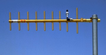
A Yagi antenna has several elements arranged in echelon. They are connected together by a long element, called the boom. The boom carries no current. If the boom is an insulator, the antenna works the same.

The rear-most element is called the reflector. The next element is called the driven element. All the remaining elements are called directors. The directors are about 5% shorter than the driven element. The reflector is about 5% longer than the driven element. The driven element is usually a folded dipole or a loop. It is the only element connected to the cable. Yet the other elements carry almost as much current.
The Yagi is the most magical of all antennas. No attempt will be made here to explain why it works. The more directors you add, the higher the gain becomes. Gains above 20 dBi are possible. But the Yagi is a narrowband antenna, often intended for a single frequency. As frequency increases above the design frequency, the gain declines abruptly. Below the design frequency, the gain falls off more gradually. When a Yagi is to cover a band of frequencies, it must be designed for the highest frequency of the band.
An antenna has an aperture area, from which it captures all incoming radiation. The aperture of a Yagi is round and its area is proportional to the gain. As the leading elements absorb power, diffraction bends the adjacent rays in toward the antenna.




 Saya seneng tentang transmisi radio, Microwave devices dan Antenna. Alumni IT Telkom lulus 2006, dan asal dari Cepu Jawa Tengah.